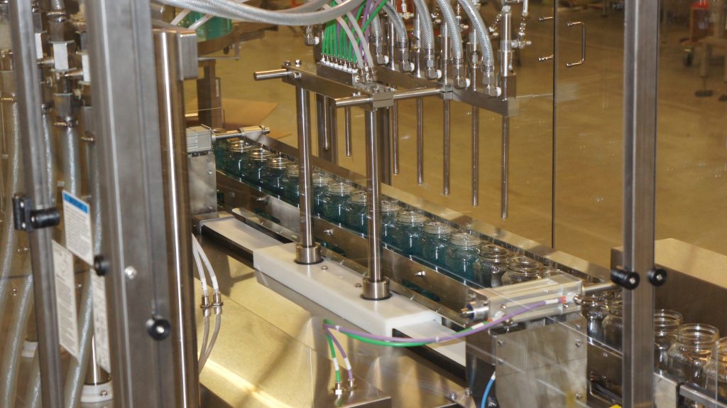
Filamatic has developed an integrated packaging system comprising of a non-explosion resistant FILAMATIC® Model AW-4 air wash system, an intrinsically-safe FILAMATIC® Model DFS-X filling system, and an intrinsically-safe beltwheel-style capping machine. This liquid filling and capping system is designed to air clean, fill, and cap containers at production rates of up to 40-45 containers/minute. The containers were being filled with an alcoholic beverage with fill volumes of 750ml.
First, the containers are carried to the cleaning area on the conveyor assembly and are held in position by a container indexing mechanism. A centering mechanism aligns the cleaning nozzles with the container neck openings. During the cleaning process, the nozzles descend into the containers and discharge a stream of compressed air to dislodge dirt, dust, and other small particles. The dust and other particles are then extracted and deposited into a storage tank. Once the nozzles have been with
drawn and the cleaning process is complete, the indexing mechanism releases the containers to travel downstream to the filling system.
Next, the containers are carried through the filling area by the continuous-motion feed screw which helps to eliminate sloshing/spilling due to the large neck opening of the jar. The filling nozzles are mounted on a walking beam assembly that tracks the movement of the containers through the filling area. During the filling process, the nozzles drop into the containers to a point roughly ½” above the bottom and rise in unison with the level of the liquid during the filling cycle. This technique is called bottom-up filling which is used to minimize any splashing or foaming that can occur. Once the nozzles have been withdrawn and the filling process is complete, the indexing mechanism releases the containers to travel to the capping system.
Last, containers are received, single file, in the capping zone on the integral conveyor assembly. As they enter the beltwheel capper, the containers enter gripper belts. Once in the gripper belts, the containers are carried through the cap pick-off and stabilization assembly at the end of the feed chute and the three (3) sets of tightening wheels. The containers are then released by the gripper belts to travel downstream to the labeling machine.
Stay tuned to next week’s blog that further explains each machine’s capabilities.
Read Part 2 of this Blog.

